Setting up linkages by Dr Colin MillPublication: W3MH issue 2I know last time I promised to talk about how the main rotor generates lift but our editor has had
a number of requests for articles aimed at the beginner. He suggested that I do 'something' about
setting up linkages so here it is.
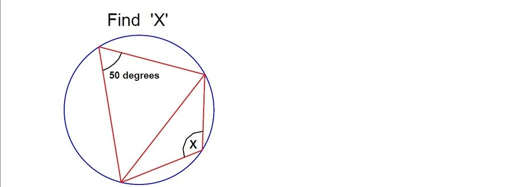
OK, do you need to read this? Try this simple test.
Find 'X'
1. If your answer was 130 degrees you might want to go and read Bruce Naylor's article instead.
2. If your answer was 'in the bottom right hand corner' you may feel more at home with the Baywatch
home page.
3. If your answer was anything else and you are a heli beginner (and especially if you haven't a
computer radio) read on!
First lets look at the geometry of the linkages themselves. I know this sounds boring but a few
minutes spent understanding this can save a lot of wasted time in setting up a helicopter. This is
because the linkage geometry usually introduces non-linearities in the controls, some of which we
can use and some we can well do without.

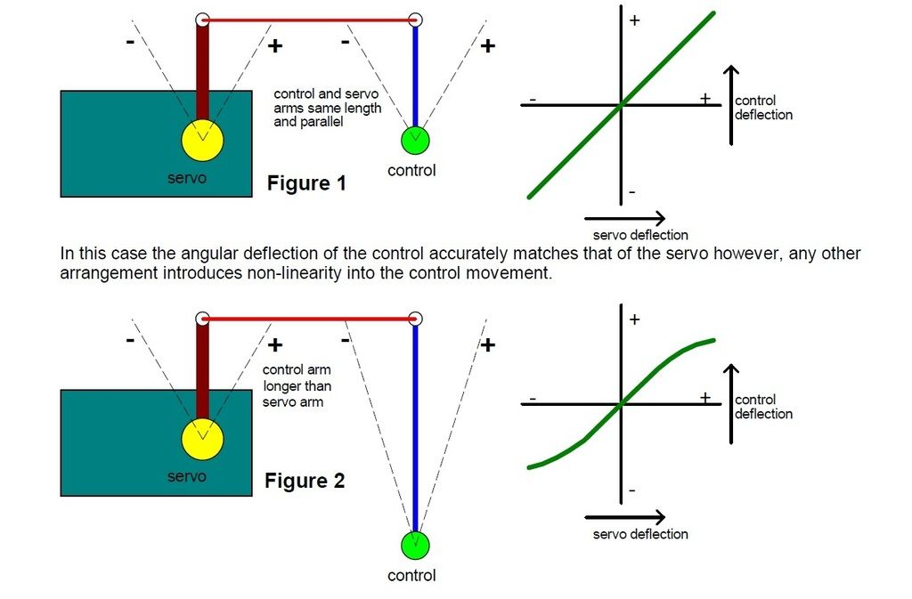
In figure 2 we have a control arm that is longer than the servo arm. If course, the angular
movement of the control is now less than that of the servo but the sensitivity of the control
movement falls off near the extremes of movement.

Conversely, a control arm shorter than the servo arm moves through a bigger angle than the servo
with an increasing sensitivity towards the ends of the servo travel (see figure 3).

Even if we stick to having the servo and control arms the same length we can get non-linear control
movements. Here in figure 4 the shorter-than-ideal push-rod causes a bigger movement of the control
arm when it is being pulled towards the servo than when it is being pushed away. The reverse is
true with an over-length pushrod. Now we could go through all the combinations of long and short
control arms with long and short push-rods but starting from these diagrams I guess you can
probably see what these combinations are going to do.
Now, if you look at the linkages on a real model helicopter things look much worse than these
simplified diagrams. For a start, the servo and control arms may well rotate in different planes
making it harder to see what's going on. Usually the control gets passed through several linkages
before it gets where its going.
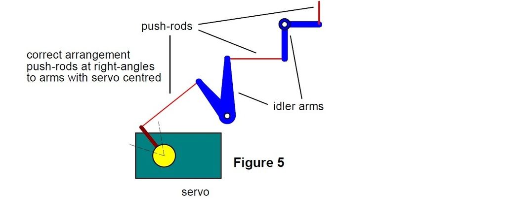
As a first rule, with the servo in the middle of its travel get the push-rods at right angles to
the arms like this

***** PHOTO 1 (left side of Concept) HERE PLEASE ******** CAPTION:-
Cyclic control linkages. The roll servo is mounted vertically at bottom left and fore-aft cyclic
servo is mounted horizontally (picture centre). Note the pushrods are at right-angles to servo
arms and bellcranks.
******************************************************************
******PHOTO 2 (tail gearbox and bellcrank) HERE PLEASE********* CAPTION:-
Sometimes compromises in the linkage geometry have to be made. Ideally this bellcrank should be
right-angled.
******************************************************************
******PHOTO 3 (Concept Collective linkage) HERE PLEASE********* CAPTION:-
Here the bellcrank angle has been dictated by the need to clear the sideframe. Unfortunately, to
get the pushrod to the servo at the right angle to this bellcrank it needs to be attached directly
to the output shaft without any arm at all. This give perfect linearity but leaves the pitch range
woefully short.
*******************************************************************
There's no excuse for not getting the servo arm pointing in the right direction. The servo
manufacturers have provided a really fine adjustment. Taking Futaba as an example, they use a 25
tooth spline on the output shaft of their servos. Lets assume we are using a six arm star on the
servo. If you move the star round four points on the spline you move it 4/25 of a turn or 57.6
degrees. Since the arms are 60 degrees apart the effective movement of the star is just 60-57.4 or
2.4 degrees. This is only about 3% of the total servo movement.
In selecting the servo arm length the required control throw is of course the primary factor.
However, where you have a choice, use the longest arm length you can. This means that the forces on
the push- rods, ball links, servo output shaft bearings, and servo mounts are all minimised. By
using long arms you also minimise the effect of any slop in the bearings or links and any flexing
of the helicopter frame or servo mounts. So even on the throttle linkage use the outermost hole on
the throttle arm. The collective pitch control probably generates the highest servo loads and so
long arms are most important in this linkage. The longer the arms the softer the servo mountings
can be and the less grief the servos will have to put up with. However, the effect of backlash in
the servo gears is not changed by arm length.

How you go about setting up your linkages will depend quite a bit on the facilities you have on
your
radio. Computer sets certainly have facilities that make life easier but a computer set should not
be seen as a substitute for making a decent job of setting up the linkages though there are quite a
few flyers I've seen who seem to treat them this way. I think it is far better to get your
linkages set up well first, with the transmitter at its default settings, and then use its
facilities to fine tune things.
If you have a good computer set then you have such facilities as 'travel volume' by which the
throws (either side of centre) can be independently adjusted for each servo. This allows you to
fine-tune the total travel of each control without fiddling about with servo arm lengths. Because
it can be separately set for each direction of throw it can also be used to compensate for unequal
travel such as seen in figure 4. 'Exponential' is a facility which allows the sensitivity of the
controls to vary between the mid stick position and full travel. This allows controls to be made
fairly insensitive to stick movements near the middle while retaining full control authority at
full stick. 'Exponential' can also be used to overcome the sort of non-linearity in linkage seen in
figure 2.
Next time I'll (hopefully) look at setting up the collective pitch range.


 Similar topics (3)